
(English)
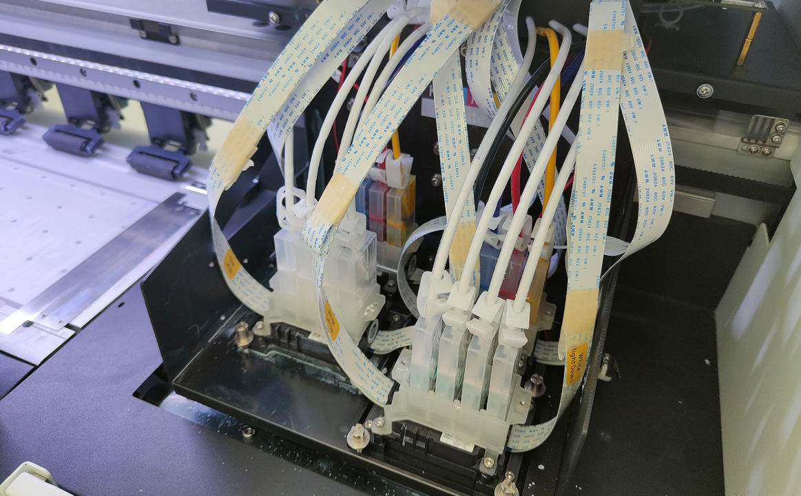
Executive Summary & Technical Brief
Ink output failure during the initial loading cycle or automated software cleaning is primarily caused by vacuum seal failures in the capping station, localized air locks inside the printhead dampers, or solenoid pump degradation within the waste ink system. When a digital printing machine runs a cleaning cycle but draws zero fluid, the issue is fluid-mechanical rather than a permanent nozzle clog. Operators must immediately inspect the mechanical alignment between the capping top rubber and the printhead nozzle face, manually purge air channels via negative pressure suction, and ensure the waste pump lines remain unrestricted.
The automated ink loading and cleaning system in industrial commercial printers relies strictly on negative pressure hydraulics. If any section of the fluid path from the bulk reservoir tanks to the waste lines admits ambient air, the system loses its vacuum, resulting in incomplete ink flow or a completely blank nozzle check.
Verify Capping Station Mechanical Alignment: When the printhead carriage parks for cleaning, the rubber rim of the capping assembly must form an airtight seal around the perimeter of the nozzle plate. If the cap is warped, dirty with dried crust, or physically misaligned, the suction force drops to zero.
Isolate Damper Air Accumulation: During initial ink loading, air frequently becomes trapped inside the transparent body of the ink damper. This air pocket acts as a pneumatic cushion, absorbing the pump’s suction pressure instead of pulling fluid from the line.
Inspect the Peristaltic Waste Pump: The mechanical pump below the maintenance unit must physically compress the silicone tubes to draw waste fluid through the system. Kinked, ruptured, or hardened waste tubes instantly disable ink movement.
Examine One-Way Fluid Valves: For machinery equipped with sub-tank positive/negative pressure valves, any electrical or mechanical failure in the solenoid coils will completely block the industrial printer carriage ink supply paths during prime cycles.
The technical matrix below categorizes specific mechanical anomalies encountered during fluid setup, along with verified corrective procedures:
| Operational Failure Mode | Probable Engineering Root Cause | Corrective Technical Action | Maintenance Level |
| Pump spins during cleaning but no ink flows to waste lines | Gap or vertical misalignment between printhead nozzle face and cap top. | Calibrate the mechanical height of the capping station stack; clean rubber seal contours. | Weekly / Post-repair |
| Ink flows backward into the supply lines after a cleaning cycle | Damper membrane structural fatigue or faulty one-way ink line check valve. | Replace the affected ink damper assembly; inspect lines for micro-pinhole air leaks. | Semi-annually |
| Only specific color channels fail to prime during initial loading | Air lock trapped inside the localized channel damper or printhead manifold. | Connect a syringe to the bottom of the damper and manually draw 5 mL of ink to remove air. | On initial machine setup |
| The capping station overflows with ink during automated cleaning | Severe blockage inside the waste ink lines or failure of the peristaltic pump rollers. | Use a syringe to flush cleaning solvent through the waste tubes to clear dried buildup. | Monthly inspection |
| Nozzles drop out completely after executing a "Heavy Cleaning" | Excess negative pressure has sucked air upward into the printhead nozzle chambers. | Let the machinery idle for 15 to 30 minutes to allow ink pressure to stabilize naturally. | As needed |
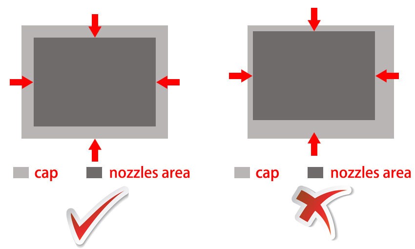
Running multiple software cleaning cycles consecutively causes the peristaltic waste pump to continuously pull ink from the nozzles. If the ink delivery system cannot supply fluid fast enough to match this high-velocity suction, it creates a temporary high vacuum inside the printhead manifold. This negative pressure draws ambient air backward through the microscopic nozzles, causing extensive air locks and channel dropouts. Always allow a 5-minute stabilization period between cleaning runs.
An air lock is confirmed when the waste pump successfully draws ink into the maintenance station during a cleaning cycle, but the subsequent nozzle test sheet displays an entire color channel completely missing. Conversely, a true physical printhead clog typically manifests as scattered, missing lines in specific areas that remain in the exact same positions across multiple test prints.
To resolve a blocked waste tube structure, use a manufacturer-approved industrial purging solvent or a mild water-based glycol surfactant flush. Avoid using aggressive chemical solvents like pure acetone, toluene, or high-concentration isopropyl alcohol. These chemicals degrade, harden, and split the flexible silicone or polyurethane tubing lines used in industrial waste ink assemblies, leading to permanent vacuum leaks.
 WhatsApp me


